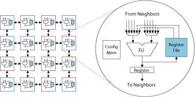
CGRAs consist of an array of a large number of function units (FUs) interconnected by a mesh style network. Register files are distributed throughout the CGRAs to hold temporary values and are accessible only by a subset of FUs. The FUs can execute common word-level operations, including addition, subtraction, and multiplication. In contrast to FPGAs, CGRAs have short reconfiguration times, low delay characteristics, and low power consumption as they are constructed from standard cell implementations. Thus, gate-level reconfigurability is sacrificed, but the result is a large increase in hardware efficiency.
A good compiler is essential for exploiting the abundance of computing resources available on a CGRA. However, sparse connectivity and distributed register files present difficult challenges to the scheduling phase of a compiler. The sparse connectivity puts the burden of routing operands from producers to consumers on the compiler. Traditional schedulers that just assign an FU and time to every operation in the program are unsuitable because they do not take routability into consideration. Operand values must be explicitly routed between producing and consuming FUs. Further, dedicated routing resources are not provided. Rather, an FU can serve either as a compute resource or as a routing resource at a given time. A compiler scheduler must thus manage the computation and flow of operands across the array to effectively map applications onto CGRAs.
Example of a Coarse-Grained Reconfigurable Architecture

We propose a modulo scheduling technique for CGRA architectures that leverages graph embedding commonly used in graph layout and visualization, referred to as modulo graph embedding. Graph embedding is a technique in graph theory in which a guest graph is mapped onto a host graph. With CGRAs, scheduling is reduced to placing operations of a loop body on a three dimensional grid. The three dimensions consist of the FU array that comprises two dimensions and the time slots of a modulo scheduled loop that form the third dimension.
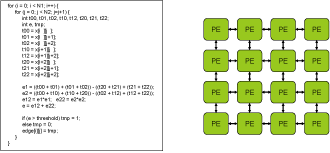
Phase 0: Target Application(sobel) and CGRA
|
|
Innermost loop of an application is selected to be executed on CGRA. With the abundance of computation resources, CGRA can efficiently execute compute intensive part of the application. Scheduling difficulties lie in the limited connectivity of CGRA. Without careful scheduling, some values can be stuck in nodes where they cannot be routed any further. |
Phase 1: Preprocess DFG and Initialize Scheduling Space
|
|
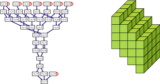
Preprocessing is performed on dataflow graph of the target application. It includes identifying recurrence cycles, SSA conversion, and height calculation. Operations are then sorted by their heights and scheduling algorithm is applied to the group of operations with the same height. To guarantee the routing of values over the CGRA interconnect, scheduling space is skewed in a way that slots on the left side of CGRA are utilized first. Since slots on the left are utilized beforehand, operands can be easily routed to the right side of CGRA. |
Phase 2: Construct Affinity Graph
|
|
An affinity graph is constructed for each group of operations that have same height in DFG. The idea here is that placing operations with common consumers close to each other. By placing operations with common conumers close to each other, routing cost can be reduced when their consumers are placed later. Affinity values are calculated for every pair of operations in the same height by looking at how far their common consumers are located in DFG. In an affinity graph, nodes represent operations and edges represent affinity values. High affinity values between two operations indicate that they have common consumers in a short distance in DFG. |
Phase 3: Search Optimal Placement
|
|
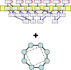
In this step, operations are placed on CGRA in a way that affinity values between operations are minimized. Scheduling of operations is converted into a graph embedding problem where an affinity graph is drawn in 3-D scheduling space minimizing total edge length. In the example on the left, nodes are placed in the scheduling space so that total edge length is minimized, giving more weight to edges with high affinity values. When scheduling operations in the next height, routing cost can be effectively reduced since producers of the same consumer are already placed close to each other. |
Phase 4: Update Scheduling Space
|
|
After getting an optimal placement of operations in one height, the scheduling space is updated so that unused slot can be used in later time slots. Then, scheduler proceeds to next group of operations. |
Relevant Publications
- None.
Page last modified January 22, 2016.


