
Heterogeneous multicore systems -- comprised of multiple cores with varying capabilities, performance, and energy characteristics -- have emerged as a promising approach to increasing energy efficiency. Such systems reduce energy consumption by identifying phase changes in an application and migrating execution to the most efficient core that meets its current performance requirements. However, due to the overhead of switching between cores, migration opportunities are limited to coarse-grained phases (hundreds of millions of instructions), reducing the potential to exploit energy efficient cores.
Composite Cores is an architecture that reduces switching overheads by bringing the notion of heterogeneity within a single core. This architecture pairs big and little compute uEngines that together can achieve high performance and energy efficiency. By sharing much of the architectural state between the uEngines, the switching overhead can be reduced to near zero, enabling fine-grained switching and increasing the opportunities to utilize the little uEngine without sacrficing performance. An intelligent controller switches between the uEngines to maximize energy efficiency while constraining performance loss to a configurable bound.
Composite Cores Architecture
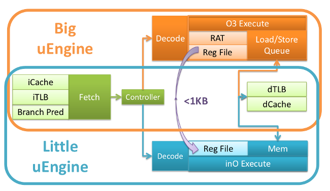
A Composite Core consists of two tightly coupled compute uEngines that together can achieve high performance and energy efficiency by rapidly switching between the uEngines in response to changes in application performance. To reduce the overhead of switching, the uEngines share as much state as possible. As Figure 3 illustrates, the uEngines share a front-end, consisting of a fetch stage and branch predictor, and multiplex access to the same L1 instruction and data caches. The register files are kept separate to minimize the little µEngin's register access energy.As both uEngines require different control signals from decode, each uEngine has its own decode stage. Each uEngine has a separate back-end implementation, one striving for high performance and the other for increased energy efficiency. However, both uEngines multiplex access to a single L1 data cache, again to maximize shared state and further reduce switching overheads. The register file is the only state that must be explicitly transferred to switch to the opposite uEngine.
The big uEngine is similar to a traditional high performance out- of-order backend. It is a superscalar highly pipelined design that includes complicated issue logic, a large reorder buffer, numerous functional units, a complex load/store queue (LSQ), and register renaming with a large physical register file. The big uEngine relies on these complex structures to support both reordering and speculation in an attempt to maximize performance at the cost of increased energy consumption.
The little uEngine is comparable to a more traditional in-order backend. It has a reduced issue width, simpler issue logic, reduced functional units, and lacks many of the associatively searched struc- tures (such as the issue queue or LSQ). By only maintaining an architectural register file, the little uEngine eliminates the need for renaming and improves the efficiency of register file accesses.
Reactive Online Controller
The decision of when to switch is handled by the Reactive Online Controller. Our controller attempts to maximize energy savings subject to a configurable maximum performance degradation, or slowdown.
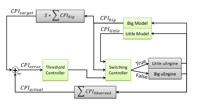
To determine the appropriate core to minimize performance loss, the controller needs to 1) estimate the dynamic performance loss, which is the difference between the observed performance of the Composite Core and the performance if the application were to run entirely on the big uµEngine; and 2) make switching decisions such that the estimated performance loss is within a parameterizable bound. The controller consists of three main components: a performance estimator, threshold controller, and switching controller.
The performance estimator tracks the performance on the active uµEngine and uses a model to provide an estimate for the performance of the inactive uµEngine as well as provide a cumulative performance estimate. This data is then fed into the switching controller, which estimates the performance difference for the following quantum. The threshold controller uses the cumulative performance difference to estimate the allowed performance drop in the next quantum for which running on the little uµEngine is prfitable. The switching controller uses the output of the performance estimator and the threshold controller to determine which uµEngine should be activated for the next quantum.
Relevant Publications
Page last modified January 22, 2016.